Hey there. A long pause, and now am back again. This time, a really awesome tutorial for you. Advanced hobbyists like me (and you, of course, 😉) love to play with microcontrollers. And the most famous microcontrollers for beginners are AVR series from Atmel™. Almost all beginners in microcontroller-world have their Arduino boards lying on the work table. Because it is so much easy, so much fun, and so much famous. Here I explained How to Burn Programs In Your AVR Microcontroller Using An Arduino. By this, you won’t need to purchase a costly AVR programmer if you already have an Arduino. And I guess you already have one. Let’s start.
Please Note: Here you won’t need any external crystal to be attached. Neither needs the painful process to optimize “bootloader” for your standalone AVR. Just connect your Arduino to the microcontroller, and start uploading codes.
Things You Need (NOT much)
- A breadboard
- 6 jumper wires and some extra wires.
- An Arduino board. ( I used Arduino UNO, But ANY Arduino Model Should Work)
- A LED and a 220 ohms resistor.
- 10 microfarad capacitor .(only if you are using older Arduino boards such as Duemilianove or NG, which don’t have auto-reset feature).
- And of course the target AVR. Here I used ATmega8-16PU.
[STEP 1] Upload arduinoISP Sketch on Arduino Board
The first step is to upload the ArduinoISP sketch to your Arduino to make it act as ISP. Well, what is ISP? It refers to In-circuit Serial Programmer. To learn more, go here.
It’s located under File >> Examples >> ArduinoISP.

Select Sketch in Arduino IDE
Ensure that the Board and Serial Port configuration is correct (under Tools), and then press Upload.
To check Serial Port, go to tools >> serial port. (for example, it may be “COM4 (Arduino UNO)” ).

Port Selection Arduino IDE
Note down that serial port number somewhere, soon you gonna need it.
[STEP 2] Open Command Prompt (In Windows OS)
Press “Windows + R” and type “cmd”, then hit enter. When command prompt is opened, it will show you the root directory. it may be C:\> , or may be anything like C:\xx\yy\zz> . for me, it is C:\Users\Avra Mitra>.
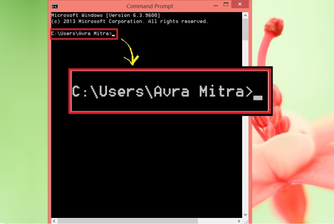
Root Directory
Whatever the root directory is, just note that down somewhere as very soon you gonna need it.
[STEP 3] Required Downloads
Now you need to download a few things to write programs. I have used programmer’s Notepad 2 (PN2) for writing codes. It came with WinAVR, an AVR toolchain.
Download Links:
WinAVR: (Windows) [Download⇓], (Mac) [Download⇓], (Linux) [Download⇓]
Makefile: (GoogleDrive) [Download⇓], (MediaFire) [Download⇓]
On-line Fuse Calculator: [Go Here⇒]
[STEP 4] Installation of winAVR (only help for windows OS is covered for now)
Start installing winAVR and make sure if all three dialogue boxes are checked while installing. Don’t change the installation directory from the default one, that is C:\winAVR.
[STEP 5] Opening toolchain apps ( MFile[winAVR], programmer’s notepad[winAVR])
We need only two components of WinAVR toolchain. One is MFile and other is Programmer’s Notepad 2.
After installation done, you won’t see the installed components on the desktop. So, press “Windows+ S”, and search with keyword “winavr”.

Search in Windows 8.1
You will have multiple results. But as already said, you’ll need two apps, MFile[winAVR], and programmer’s notepad[winAVR]. Ignore rest of them.
[STEP 6] Editing “MakeFile”
First of all, we have to know what a Makefile is. Go here to know about Makefile. In a nutshell, Makefile is a file without any extension. Most often, the makefile directs make on how to compile and link a program.
Hence, it’s really really important to configure an appropriate Makefile. Without deep knowledge of AVR and C language, you can’t make a Makefile. So I included a template. You just need to edit it as per your AVR IC.
1. Open MFile[winAVR].

Open Mfile application
2. Now, Makefile >> Enable editing of makefile >> (select it.).
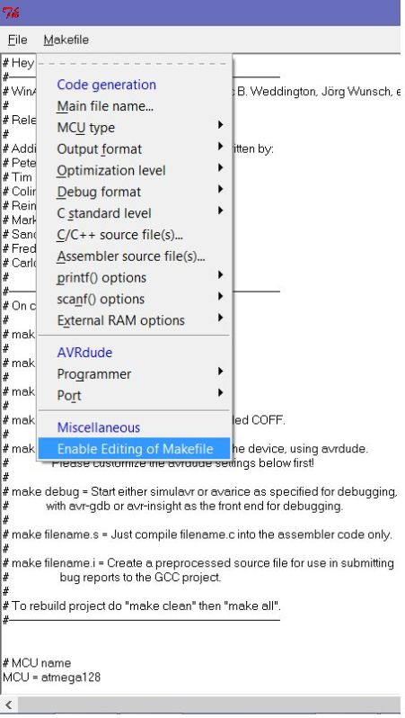
Enable editing
3. Now, File >> Open >> ( now navigate to where you have downloaded the Makefile).
4. Now, you need to edit it. Only the marked areas are needed to be changed by you.

Edit These Things
Here we need some a little bit explanation about the editable parameters. So, let’s do it.
DEVICE: Here you should write down your AVR’s name. In my case, it’s “atmega8”. You may use other AVR. So, you HAVE TO change the name of the device if you use a different one like atmega328 or atmega168. Else there’ll be a lot of problems.
CLOCK: This is clock speed of the device. The maximum internal clock speed of atmega8 is 8MHz or 8000000Hz. You should know your AVR’s clock speed from the datasheet.
NOTE: THE VALUE WRITTEN IN MAKEFILE CAN BE OVER-RIDDEN BY RE-DEFINING NEW VALUE
      IN PROGRAM (MAIN.C). SO, IT'S WISE TO PASS MAXIMUM VALUE IN MAKEFILE.
      IF NO VALUE IS MENTIONED IN MAIN.C, PROGRAM WILL BE EXECUTED IN A
      CLOCK SPEED MENTIONED IN MAKEFILE.
PROGRAMMER: In this section, the name of programmer device, COM port number and speed of communication is mentioned. “Arduino” is the programmer. No need to change it. All we are concerned about are “COM” port number and “baud rate”. The “COM” number should be the number where your Arduino is connected to and you already wrote it down from “Arduino IDE”. Now, what if next time you connect your Arduino and a different COM port is assigned to it by OS? No problem. While uploading code using command prompt (discussed later), we’ll always mention the current COM port. So, once you write a COM port value to Makefile, it’s done. No need to change it in future. Now come to “Baud Rate”. It implies speed of communication between uploader and target device. As per “arduinoISP” code, the baud rate is set to 19200 i.e 19200 Bits per second. You can set it to other available values (9600, 115200 etc.) but then you need to change the value in “arduinoISP” code also. The process is simple. Just open arduinoISP code in IDE, and do the following change.
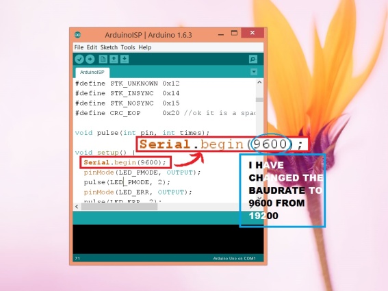
Change Baud Rate in arduinoISP Sketch
OBJECTS: Keep it unchanged. We have nothing to do with it. “main.o” is default one.
FUSES: OK, now it’s a very important thing we gonna deal about. Setting up correct fuse bits are extremely important. Improper setting of fuse bits may brick your AVR device. So, what “fuse” is? The fuses determine how the chip will act, whether it has a bootloader, what speed and voltage it likes to run at, etc. Note that despite being called ‘fuses’ they are resetable and don’t have anything to do with protection from overpowering (like the fuses in a home). Go here to learn more, it’s important.
Go to the online fuse calculator link I have given and enter your device’s name. Then chose clock speed. Please note, the fuse settings I have given in my “Makefile” is for 1MHz clock speed. So, you have to change the fuse settings if you want to run your AVR at a different speed. There is a procedure to override the Makefile’s fuse settings during uploading compiled program (.hex file) to AVR. But I have not discussed it here. Check the slideshow below:
All set. now save the file to your root directory. Don’t save it any different place.(In step 2 I have told you to note down the root directory from command prompt. )
[STEP 7] Write a Program In C
Time to make a program that should be compiled and uploaded to AVR.
- Open Programmer’s Notepad[winAVR]. Select C/C++ from drop down.
![Select Programming Language [C in this case]](https://riktronics.files.wordpress.com/2016/07/pn1.png?w=540&h=649)
Select Programming Language [C in this case]
//Simple code by riktronics to toogle an LED at 0.5Hz
//visit riktronics.wordpress.com
//LED is connected at PD6 of ATmega8
//Read datasheet of atmega8 for more details
#define F_CPU 1000000
/* CPU frequency re-defined as 1MHz for proper time calculation in delay function */

#include <avr/io.h>
#include <util/delay.h>

int main()
{
 DDRD |= (1 << PD6); // make PD6 an output

 while(1)
 {
 PORTD |= (1 << PD6); // turn on led at PD6
 _delay_ms(1000); // delay for a second
 PORTD &= ~(1 << PD6); //turn off led at PD6
 _delay_ms(1000); // delay for a second

 }

 return 0; // the program executed successfully
}
The code is set to blink a LED connected to PD6 PIN at 0.5 Hz frequency. The LED will go ON, remain ON for 1 second, then go OFF, remain OFF for 1 second. This thing will go on infinitely. You need good knowledge in C programming and have to learn bitwise operators and their usage to make your own codes. At the same time, reading datasheets of the microcontroller is important also. Right now I am not going to explain how to write codes, but I have a wish to do it soon. In the mean time Google about it and start learning.
3. Now go to File >> Save >> (now save it to root directory, where you have also saved the Makefile). Name the file “main.c“, and chose “all formats”. Then save it. The name MUST BE main.c.
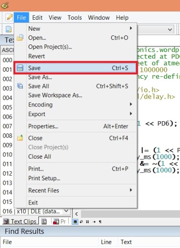
save
NOTE: Makefile and main.c must be in the same directory. And the directory must be root directory that you have found in command prompt in step 2.
After you have saved it, now go to Tools >> [winAVR]Make All >> (click).
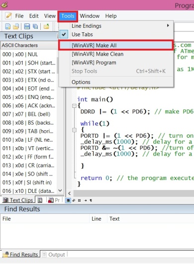
Compile Program by “Make All” Option
Compiling is successfully done if you have not done things wrong. If all is OK, then you can see it on programmer’s notepad’s “Output” window.

Output Window
Now if you go to the directory where Makefile and main.c are stored, you’ll see 3 other files. main.hex, main.o, makefile.bak. The main.hex file will be uploaded to AVR.
[STEP 8] Circuit Diagram
These are the minimum circuit diagrams to program an AVR using Arduino. I have given circuits for three very common AVRs. ATMega328p, ATMega8 and ATTiny2313. But following the below PIN connection, you can easily program any AVR or ATTiny.
Just place your IC in a breadboard, place the Arduino besides breadboard. Use jumper wires to make connections. Then connect Arduino to PC. Check below slideshow for the circuit diagram.
ATMEGA8 PIN CONFIGURATION:

ATMega8 PIN Configuration
CONNECTION:
PIN MOSI (17) of AVR to digital PIN 11 of Arduino.
PIN MISO (18) of AVR to digital PIN 12 of Arduino.
PIN SCK (19) of AVR to digital PIN 13 of Arduino.
PIN RESET (1) of AVR to digital PIN 10 of Arduino.
PIN VCC (7) of AVR to 5V PIN of Arduino.
PIN GND (8, 22) of AVR to GND PIN of Arduino.
To know the PIN configuration of your AVR, go to Atmel’s website. In the search bar, type your AVR’s name. Now, chose appropriate search result and select “datasheet” option. Download it and open. There you can see the PIN configuration.
You may need to add a 10 microfarad capacitor between RESET and GND PIN in Arduino, only if your Arduino is an older version and doesn’t support auto-reset. But if you are using UNO R3, MEGA or any newer version, you won’t need it.
Make the circuit on a breadboard without any loose connection. Below is my circuit. As the AVR is already programmed, the green LED is lit up.

Real Image
[STEP 9] Uploading Program Using AVRDUDE
Now be very attentive and careful. Because, in following steps, we going to upload the compiled code to AVR using AVRDUDE. Urrgh, what is AVRDUDE? Okay, AVRDUDE is a command line software that comes with winAVR and makes the uploading process. To call AVRDUDE you need to open the command prompt and then put correct commands to make it work as it is a command line software.
In AVRDUDE, we will define programmer type, AVR name, COM Port, baud rate (speed of uploading), Upload command, desired action (read, write or erase), memory location (flash or EEPROM), the defined .hex file. Fuse bits can be also defined here to override one in Makefile. But now it is not discussed.
Know Available Commands:
To know available commands, simply call avrdude by opening the command prompt and there typing “avrdude” without quotes followed by “Enter” key.
avrdude

Available Commands
Know Your AVR’s Code Name
You know your AVR’s name, no doubt, but you don’t know it’s code name which must be mentioned in AVRDUDE command line to upload the code. How can you know it? Okay, you need to put a command, which will show you code names of all AVRs.
open command prompt >> (you can see the root directory is already written on-screen) >> type the following code and press enter.
avrdude -p ?
It will open a chart of AVR names and corresponding code names.
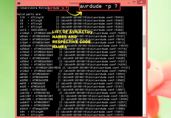
AVR Name
Now you know your chip’s name. Replace “?” after -p with your chip’s name. If AVR is atmega8, command line will be,
avrdude -c arduino -p m8
The “-C arduino” defines that programmer device is Arduino.
Set COM Port
I think you have noted down the COM Port already. Now make sure if your Arduino is connected to PC and AVR on breadboards is connected to Arduino. You can also go to “Device Manager” in Windows and double-click on “COM and LPT”. A dropdown will be opened and there you can find the COM port assigned for your Arduino.
Now put the below command on Command Prompt, (Don’t forget to replace my AVR’s code name with your AVR’s and my COM Port with yours COM Port). Now press enter.
avrdude -c arduino -p m8 -P COM4
Set Device, Baud Rate, COM port
I repeat again, type correct AVR name and COM Port. Don’t just copy paste this code.
Now it may give you a message like “your chip’s signature is blah blah
expected atmega8 signature is blah blah and blah
check your chip connection or use -F to avoid it”.

(Older Screenshot) Set COM Port
Do nothing. Just ignore it. Go to next step.
But, if you get any error message, the fault is yours. double-check all connections. set correct AVR name and COM Port.
Upload HEX file to AVR
You are almost done. Now it’s time to upload the .hex code that is generated in root directory by programmer’s notepad[winAVR] (at that moment when you have clicked on “make all” option).
Now in the command prompt, you need to put the command to upload the hex file (main.hex). Use the below command but don’t forget to change chip name and COM Port as per your AVR and PC, then press enter.
avrdude -c arduino -p m8 -P COM11 -b 9600 -U flash:w:main.hex

(Older Screenshot) Command To Upload Program

(Older Screenshot) Upload Process
The baud rate is set here 9600 (In images it’s 19200 as older screenshots are used here). You can change it to other values, but at the same time, you have to change it in Makefile and arduinoISP sketch.
Done, the code is uploaded.
Now you will see the LED on the breadboard is blinking. Fine. Anytime you can change or modify the code. For example, change delay times and re-upload code.
CAUTIONS:
1) MAKEFILE AND MAIN.C MUST BE IN SAME DIRECTORY AND THAT MUST BE ROOT DIRECTORY.
2) EACH TIME YOU CHANGE YOUR CODE, PREVIOUS CODE GETS OVER-WRITTEN BECAUSE TWO DIFFERENT FIES UNDER SAME FIE NAME (MAIN.C) CAN NOT EXIST IN THE SAME DIRECTORY. TO PRESERVE YOUR PROGRAM, COPY-PASTE THE MAIN.C TO SOMEWHERE ELSE BEFORE WRITING NEW CODE.
3) IF YOU WANT TO CHANGE BAUD RATE, CHANGE IT IN ALL THREE PLACES: MAKEFILE, ARDUINOISP SKETCH, IN AVRDUDE COMMAND.
4) THE FUSE SETTING GIVEN WITH MY MAKEFILE IS FOR ATMEGA8 @ 1MHz CLOCK SPEED. FOR DIFFERENT IC AND DIFFERENT CLOCK SPEED, YOU MUST CHANGE IT.
THANKS FOR READING… If you have liked it, say a warm “thanks” in comments. If you need any help regarding this tutorial, don’t hesitate. Just comment out and I’ll try my best to give a solution.
[For beginners, an awesome guidance to get started in electronics can be found HERE.]

Hello. You have taught very well. I have seen another method that the work process is very short and short. Do not you want to teach it?
LikeLike
Thanks for the great walk through
LikeLike
worked perfectly fine.
LikeLike
It is very working for me (I am using AtMega8). At first, I think it would be difficult to program AtMega using Arduino, but after I followed your tutorial, it seems very easy. Thank you.
LikeLike
Thank you for this great tutorial. I finally got my atmega328p working.
It was really helpful.
LikeLike
I’m sure everything has been configured correctly but still got those errors, any ideas ? Cheers !
https://drive.google.com/file/d/11Hc2PiXscA_KkLNt8h5S7x4FpVw_E2op/view?usp=sharing
LikeLike
I’m dure everything but still got this error, any idea ? Cheers !
https://drive.google.com/file/d/11Hc2PiXscA_KkLNt8h5S7x4FpVw_E2op/view?usp=sharing
LikeLike
Good tutorial, i folowed every step, and successfully programmed arduino progammer instead of avr chip 🙂 Ended up with 2 arduino uno blinking boards on the end 😦
LikeLike
Reading | ################################################## | 100% 0.09s
avrdude: verifying …
avrdude: verification error, first mismatch at byte 0x0000
0x12 != 0x00
avrdude: verification error; content mismatch
avrdude: safemode: Fuses OK
avrdude done. Thank you.
LikeLike
avrdude : stk 500_getsync() :not in sync:resp=0X15 error comming
LikeLike
ive been searching for a cheap easy way to program.. and this tutorial has been really helpful…hope to see more of your articles…
I would like to ask just one thing… I have an atmega16L8pu.. ive reffered the datasheet ans it tells me its identical to the atmega 16… and I don’t find any other options either in the command prompt…but when it comes to programming the thing…it doeasent respond….it tells me the device signature is 0x000000… does it mean my ic’s fried or is it my fault?
LikeLike
Hi Ramdas, thank you for your interest. Now coming to the point directly. Actually, that bad signature error (0x000000) can occur for various reasons. As per my experience, the causes are:
1)Poor connection. YES. This is the worst culprit. Even if you think, “No! my connection is damn okay!”, still there maybe slight issues and that thing prevent avrdude from connecting to your ic. Rebuild the circuit using good wires and functional breadboard.
2) In the first case, I have assumed your settings in the makefile is correct and arguments passed in AVRDUDE command line is error free. But, what if it is not so? Make sure you have entered proper IC name, baud rate, fuse settings and PORT in both makefile and AVRDUDE command line. PORT must be correct while entering in AVRDUDE.
3) Your chip is fried. Hm, sad but possible. But at the same time, it’s less likely. Try the first two troubleshooting very carefully for hours before coming to this sad conclusion.
It is really frustrating when this kind of error occurs. Don’t loose patience, don’t give up. Try, troubleshoot, get your hands dirty, and thus become a great engineer what book worms can never become.
LikeLike
thank you for the reply.. ive seen through it but seems to be not working… itried changing the breadboard but not much of a difference there…as far as the code goes all compilations went on seamlessly…except ofcourse for the ic….I thought maybe I really did fry it… os decided to swap out the ic with the atmega168a….nothing happened…errors came back the same…I tried on an atmega 16a too… it didn’t work either…. all of these chips were good so I guess all of them couldn’t have been blown..bear in mind I did make the required changes in the code and makefile as well…I tried putting a capacitor between the reset and ground but then the error changed to
avrdude: stk500_getsync not in sync resp0x00
but there are hanges in the device signature when I remove the cap
it comes anywhere between 0x000000 to 0xffffff so ithought there maybe excessive noise in the lines( my uno is very old…) so I tried pulling down all the data lines with 1k5 resistors (the largest I had on spare) and the device signature became a constant 0x000000… really confusing… don’t know what to do….hoping you can help me out here….
LikeLike
The error “stk500_getsync not in sync” occurs mainly for baud rate mismatch. Make sure that baud rate is same in Arduino code, makefile, and avrdude command line. If, Serial.begin(19200) is written in arduino code, set the same value in the makefile. Also, pass this same value in avrdude command line.
And if everything fails, download “avrdudess” from the internet. just google for it to download. This is actually a GUI version of avrdude. You can try your luck with it.
I am thinking about other troubleshooting methods and I’ll let you know as soon as I find a better solution.
Keep trying. 🙂
LikeLike
Thanks..I’ll try my luck with the dudess…
LikeLike
I was getting the same error using an atmega328p-pu, then I changed the microcontroller and everything worked fine. So my microcontroller was fried. Fortunately I have another one.
LikeLike
Do I have to use C, or can I choose another program language?
LikeLike
C is considered as the best language for embedded systems (i.e microcontroller based systems). AVR MCUs run .HEX file. When you compile a .c program, a .HEX file gets generated. If you use another language like .asm (assembly), a .HEX file is generated again. But, this time you have to use different compiler/interpreter as a C compiler can’t compile/interpret other languages to produce .HEX.
So, yes. You can use different language with different compiler/interpreter (gcc, the compiler used in my tutorial, works only for C/C++). But once the .HEX is generated, the uploading process (using AVRDUDE) remains just same.
Change/remove makefile if you are not using C and also make other required changes to produce the final .HEX file properly.
Good luck. 🙂
LikeLike
Great tutorial thank you very much 🙂 appreciate your effort
if you have post a tutorial on how to write C for micro controller please let us know
Many thank and wish you the best
LikeLike
Thanks, Nabih. I’ll try to write tutorials on C for microcontrollers in future. Actually, time is the thing that bars me from writing more. 😐
LikeLike
This is a great tutorial. I got my Atmega16 blinking in no time.
Thank you!
LikeLike
You’re welcome. 🙂 I am happy that you found it useful.
LikeLike